Article
Introduction
The FDSLoadr cable is the key element for this project. It allows our computer to talk to our Famicom Disk System hardware. Fortunately, the cable itself does not require any extra hardware between the PC and our FDS, simple straight wire connections are made between the devices. It’s the FDSLoadr software on the PC the one doing all of the heavy work.
In a nutshell, we need a suitable plug for connecting to our PC’s printer port, a reasonable length of multi-conductor cable to allow for a comfortable distance between our PC and our Famicom setup, and a suitable plug for connecting to our FDS Unit or RAM Adapter.
Getting the first two items is fairly simple. The best option is buying a parallel printer cable and cutting off the end that goes into the printer. This leaves us with a perfectly good computer plug and long cable with all the necessary wires, ready to use. Getting the last item is the difficult part. The Famicom Disk System uses a custom type of plug that is not available through electronics retailers.
The straightforward approach to this would be soldering the wires directly to the FDS drive or RAM Adapter, installing standard plugs alongside the custom ones, or severing the RAM Adapter cable and installing standard plugs on each end. I don’t recommend this approach because it involves destroying vintage Nintendo hardware, but it’s the easiest and most straightforward way of doing it.
My chosen approach to the problem does not modify our Famicom Disk System hardware in any way, preserving its aesthetics and originality, and also allows for easy hardware interchanging. Let’s get on to it.
This is how the Interface socket on the back of the FDS drive looks like:
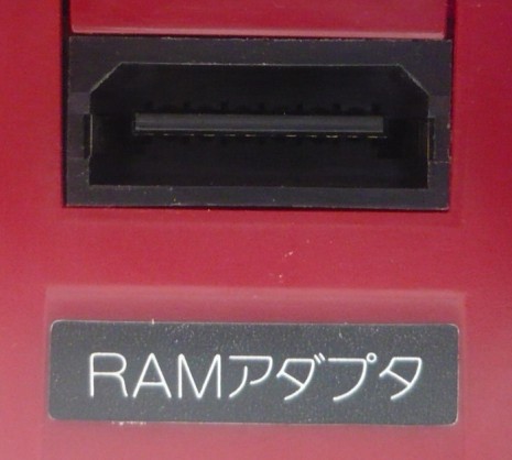
This is a custom 12-pin plug created by Nintendo, no electronics stores will carry this part because it’s not standard and not intended to be sold to the general public.
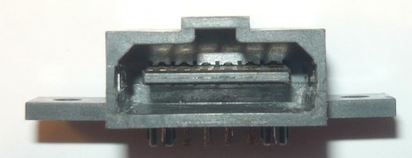
Fortunately, Nintendo reused this design on its later systems with some slight mechanical modifications.I’m talking, of course, about the AV Multi Out port, present in all Nintendo systems since the AV Famicom and all the way up to the GameCube. Here’s the AV Multi Out port from a NTSC-U SNES console:
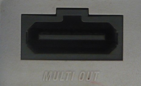
Notice the striking similarities. Both plugs contain the same number of pins in the same basic configuration. The only differences are mechanical ones: a rectangular notch was added to the top part of the socket, and the two bottom corners were angled just like the top ones. This means we can repurpose this connector for our RAM Adapter interface with minimal effort.
Conversely, we can modify Nintendo AV cables to make a Disk Drive interface. Nintendo AV cables are readily available at local gaming shops, abundant and inexpensive, giving us the perfect solution.
Unfortunately, getting the AV Multi Out socket is not as easy as getting Nintendo AV cables. It must be removed from a Nintendo system. The most sensible option would be to remove it from a broken console that can be had for cheap on eBay or laying around the house. Removing the connector from the systemboard requires soldering skills, and some manual plastic work must be done to the socket to accomodate it for FDS operation. Even with these disadvantages in play, this method produces very professional results and preserves Famicom hardware intact.
(TO DO: Insert some text about using a piece of double sided printed circuit board as a cheap alternative.)
Types of FDSLoadr cables
There are two types of FDSLoadr cables that can be built and used:
- PC to RAM Adapter Cable; for rewriting disks and playing .FDS ROM files on real Famicom hardware
- PC to FDS Drive Cable; for dumping physical Famicom disks to .FDS ROM files.
Both cables will be analyzed and documented separately.
PC to RAM Adapter Cable
To build this cable you’ll need:
- 6-ft Parallel Printer Port Cable
- AV Multi Out socket from Nintendo system
- Dremel or similar tool with fine drilling/carving bit.
- Small triangular file
- Soldering iron, electronics solder, desoldering pump or wick
- Small project box
- Scissors or wire cutters/strippers
- Hot glue gun
Converting the socket:
First, remove the AV Multi Out socket from the Nintendo system using your soldering equipment. Apply a bit of fresh solder to every pin, then heat up each pin with the iron and remove the solder with the desoldering pump or wick. Once the solder has been removed from all pins, the socket assembly can be easily removed from the motherboard.
Next, you’ll need to use your drilling and filing tools to remove the two bottom plastic corners as indicated below:
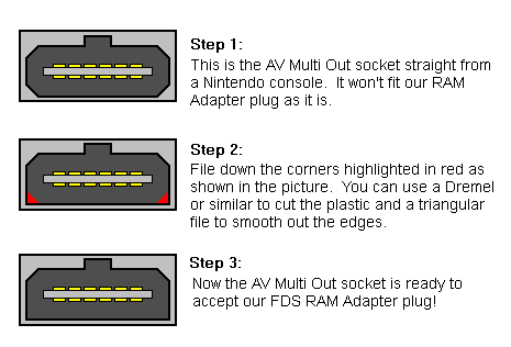
The final result should look like this (click to enlarge):
Ensure that the RAM Adapter plug fits all the way in. If not, keep filing those corners until it does. Now you’ve got a perfectly compatible RAM Adapter plug!
Preparing the Printer Cable
1. Get an old parallel PC printer cable, you can still buy them for cheap at computer stores in case you don’t have a spare lying around your old computer supplies. Take the end that plugs into the printer (usually the largest plug) and cut it off. Discard the Centronics plug and strip the insulation off the cable about an inch. Leave that end aside.
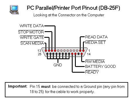
2. Take apart the plug that goes into the computer (usually held closed by screws or plastic clips). Take care of not losing any screws and other parts. You need to identify which wires correspond to which pins (you’ll notice that all the wires are nicely color coded). Before you do this, we need to take a look on how the pins are numbered:

This plug is called DB-25 (DB stands for D-Subminiature and 25 corresponds to the number of pins). The above picture corresponds to the female plug on the computer, or the back of your printer cable plug. Make sure you’re doing this correctly, you don’t want to count the pins the other way around!
Tip: If you’ve got good eyesight (or a magnifying glass), you’ll see that the pin numbers are engraved in the connector’s plastic. They’re really small and hard to see, you’ll probably need a bright source of light to be able to make them out. If you can read them, it will make everything easier.
3. Once you’ve got the pin numbers identified, make a list of what wire colors correspond to these pins:
1, 2, 10, 11, 12, 13, 14, 16, 17 and 25
(Note: It’s possible for all pins from 18 to 25 to be wired together in your particular cable. In this case, take note of the color of the only wire coming out from these pins).
4. Once you’ve got every wire color identified, desolder the wire from Pin 15 and then solder a small wire between Pin 15 and Pin 18 (or any pin between 18 and 25 for that matter). Now close the connector shell and move on to the next step.
Preparing the RAM Adapter plug
1. Take the stripped end of the printer cable, and snip off every colored wire that doesn’t correspond to the aforementioned pins on the previous step. You only want the wires for pins 1, 2, 10, 11, 12, 13, 14, 16, 17 and 25. The other wires won’t be used and trimming them will help avoid clutter, confusion and mistakes.
2. Now is when the fun stuff begins! You’ll have to solder each remaining wire to a specific pin on your modified AV Multi Out plug. For this task, I will provide standard pinout diagrams for the electronics-inclined folks and a simplified wiring diagram if reading schematics and matching pinouts is not your thing.
First, we’ll start off with the pinouts:
You’ve already color coded the wires corresponding to these pins. Now you need to match them up with the RAM Adapter connector:
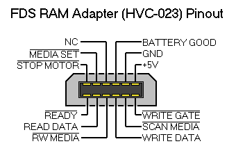
Note: The NC and +5V pins do not connect to anything.
Important consideration regarding pin connection: The above pinout shows you each pin’s function looking directly at the RAM Adapter plug. You’ll be soldering your wires to the AV plug, which bends the pins in a 90 degree angle. Looking at the front of the AV plug, pins facing down (like in the picture at the beginning of the tutorial), the bottom row corresponds to the row of pins nearest to you, and the top row corresponds to the row of pins farthest to you.
An easier way to look at this: Take the RAM Adapter plug so that its connector end is facing you (like the pinout says). Now plug the AV plug into it (so now you’re seeing the back of the AV plug), then raise the plug backwards. Now the bottom pins should be facing you, and the RAM Adapter cable should be facing down. In this position, the position of the pins you’ll be soldering on matches perfectly with the above pinout. (TO DO: I’ll probably try to make a drawing out of this if it’s hard to see.)
Now you can break out your soldering iron and start soldering each wire to the AV plug. It’s pretty simple: Just solder the wire that corresponds to GND into the pin designated as GND, then do the same with BATTERY GOOD, WRITE DATA, MEDIA SET and so on, until every wire has been used (remember that NC and +5V do not connect to anything).
Here’s the simplified wiring diagram I promised, to help clear out any confusions (click to enlarge):
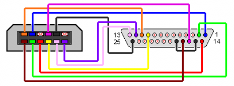
These colors were arbitrarily chosen by me, remember to use the wire colors you’ve mapped before.
Once you’ve finished soldering all of the wires, recheck your connections. Double check, Triple check that everything’s where it should be. To give you a general idea, this is how my cable looked like during the testing phase:

You can see I didn’t trim off the unnecessary wires, instead I just twisted them together and bent them out of the way. I strongly recommend cutting them off to avoid soldering mistakes and short-circuits.
Now it’s a good time to carefully test out your new FDSLoadr cable, by loading a .FDS ROM into the RAM Adapter. If it works, you can proceed to polish your creation by fitting everything into a project box. If it doesn’t work, you’ll have to check your wiring. Don’t panic if it doesn’t work on your first try. I made a mistake on my first try. I got ERR. 27’s every time. Turns out I had misplaced a pin. It’s easy to get confused when managing many colored wires and trying to visualize the pin numbers in your mind. Perseverance is your key to success here.
The Final Touches
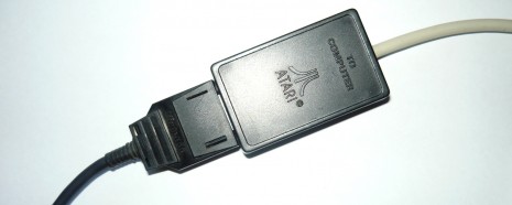
Now that your cable works, you’ll want to protect those fragile wires from touching each other and causing short circuits and from breaking due to fatigue. I recommend applying generous amounts of hot glue to the pins to keep the wires from wiggling and breaking, and for the true professional touch, enclose the plug inside a small project box. Here’s how mine turned out:
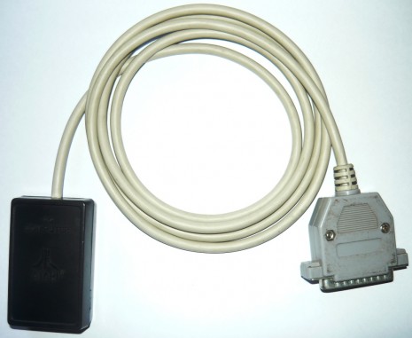
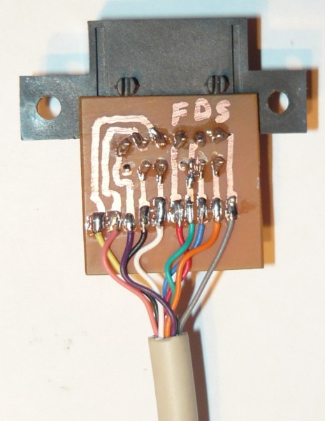
I used a small piece of printed circuit board to connect the wires neatly to the socket.
I used an old Atari Computer Switch Box. Oh the irony! I think it looks professional.
My plastic cutting skills were a bit rough, but they did the job.
(TO DO: Final thoughts)
PC to FDS Drive Cable
Coming soon (I hope).
